1.2 Chassis Options
-
Type A/B NETS Chassis/
Metric Chassi / Waterford Based Chassis
-
-
GM 1978-1987 G Body 108 inch Metric Frame with all suspension
points retained to manufacturer specs. Must be able to pass
inspection using Johnson Chassis inspection tools.
- Frame may be
fabricated forward of the front spring buckets.
-
A/B
Replacement of the rear frame from aft side of spring pocket
perch allowed. with Minimum 2x3 x 0.90
-
Replacement tubing of the rear frame must
maintain a minimum of 8 inches ground clearance.
-
Section must maintain width equal or greater
than distance between outside of rear spring
bucket. Rear frame between rails must use same
size tubing.
-
C Channel may be boxed.
- C Channel may be replaced with 0.125 square tubing .
- Minimum 2 inch X 3 inch allowed .
- 3inch X 4 inch tubing is preferred.
- Rear Shelf Metric (A/B/S)
- There is no penalty of removing or
altering the rear shelf
- Please note : removal of the shelf alters the
rear clip strength. A tie in replacement
tubing that runs from side to side in place of
the shelf is recommended..
- 1.3 Chassis replacement components
- Frame
Type A / NETS Chassis/
Type B
/S Metric
- Johnson Chassis
78-89
GM-METRIC FRAME
-
4-Link
- OEM 225lbs
- 3" X 4" x
.125 Main Frame Rails
-
(Must
be purchased through NET or
authorized chassis dealer)
- Front Clip
Type A / NETS Chassis/
Type B
/D
- Johnson
Chassis X-Y-G Metric Front Clip
-
GM-METRIC
TUBULAR REPLACEMENT
-
O.E.M
DIMENSIONS & WEIGHT
-
USES
OEM OR TUBULAR COMPONENTS
-
MOTOR
MOUNTED IN O.E.M. LOCATION OR 3” SETBACK TO # 1 PLUG
-
LOWER
A-ARM SLOTTED FOR WHEELBASE
SLUGS 0”-1/4”
-
(Must
be purchased through NETS or authorized chassis dealer)
-
Hamm
GHC 5108
-
Hamm
GHC 54108
- Howe 358-08-01 F Body Front Frame
- Engine must be at 11 inch
crank height
-
All Howe tags and logo must be in tact
- Team must contact Howe and supply inspection diagram
-
Howe
35819 Chevelle Type Front Frame C/D
Chassis
-
All Howe tags and logo must be in tact
- Team must contact Howe and supply inspection diagram
- Howe 35809 Impala Type Sub Frame
C/D
Chassis
-
All Howe tags and logo must be in tact
- Team must contact Howe and supply inspection diagram
- Any snout may be submitted for approval.
- Rear Clip
Type ANETS Chassis/
Type B/D
- Johnson
Rear Replacement Frame allowed
-
(PREFORMED
2”X 3”X .125
-
CLEARANCED
FOR BRAKE CALIPERS 15” TALL SPRING BUCKETS )
4-LINK W/BUCKETS
-
W/KICKERS
AND TRAILING ARM MOUNTS
-
Verified Johnson Rear Frame mounts unaltered will
be considered stock\
- Rear shelf
- note: removal of the shelf alters the
rear clip strength. A tie in replacement
tubing that runs from side to side in place of
the shelf is recommended..
1.4 Roll Cage / Chassis/ Frame
- Main Cage Tubing (Halo, Front and Rear Main Hoop,
Ear bar, Door Bar)
- 1 and 1/2 with minimum .120 wall tubing
- 1/3/4 with minimum .090 tubing
- Halo must be within 4 inches of front edge of roof
- Front Hoop to Ball joint measurement maximum 28
inches
- Rear Hoop to center of rear axle minimum 32 inches
- Distance from top of frame to bottom edge of rear
hoop minimum 40 inches.
- Ear bar must be no more than 6 inches forward of
rear main hoop (b Post)
- All welds must be complete
- X method for Right/Passenger side door bars is
allowed
- Drivers Door Requirements
- Minimum 4
- Must be plated with minimum .125 thickness steel
- Minimum height of door bars from frame to top of
bars, 22 inches
- Padded with proper resilient padding
- Trucks built after Feb 1 of 2016 must have
- Continuous diagonal bar extending from drivers
side top corner of rear main hoop to the base of the
rear rear main hoop on the passengers side.
- Anti bow bars must be installed to support the
diagonal brace.
- Front down tube minimum wall thickness is .083
- Must extend forward past front spring buckets
- Recommended to align with top driver's door bar
- No excessive bracing
- Aft of main hoop
- Minimum 4 back stays
- Minimum wall thickness .083
- Recommend 2 back stays align with top drivers
door bar and extend to area of rear spring bucket
- Recommend to back stays run from top of main
hoop to frame.
- Fuel cell protection bar mandatory
- Bumpers
- Single tube - front conforming to nose
- Single tube - rear conforming to bumper cover
- Must contour to body
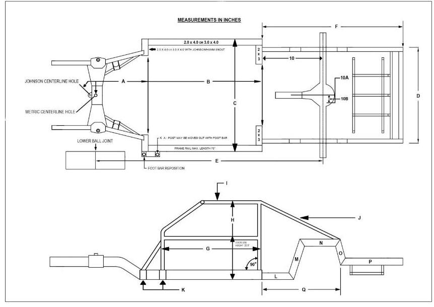
- Seekonk-Metric
- A- Centerline hole, Forward placement of snout will
use two holes for measurements. OEM - 26.5".
Johnson/Hamm - 27.125". +/- ½". Snout MUST be centered
to FRAME and REAR CLIP, NO tolerance.
B- Frame rail lengths, from snout centerline hole to end
of rail - 75" Maximum.
C- Chassis frame rails width outside to outside Max
54.0" +/- ½".
D- Rear clip outside to outside 42.0". Mounted centered
to front snout.
E- Wheelbase length 102.0" minimum. No tolerance.
F- Rear clip length 66.0". +/- ½".
G- Roll cage length, measured outside of main posts -
44.5". +/- ½".
H- Roll cage height: top of cage to bottom of chassis -
47.0". +/- ½". The cage must stand at 90 degrees
to the chassis and not go further back than frame rails
allow at 74.5". Refer to (B)
I- Roll cage halo 44.0" length / 29.5" width. +/- 1.0".
J- Down bars from main cage - top 38.0" outside to
outside +/- 1.0". Bottom attaches to end of chassispiece
(N). Bars may intersect with other bars before
connection to chassis.
K- Roll cage A-post leg and foot bar maybe moved 3.0" to
outside of main frame rail. 2” x 4” tubing .120"
wall, must be used under the repositioned bars welded
off main frame rail or in front of kickout. This is
the only portion of the cage allowed to be repositioned,
giving more leg room to the driver.
Rear clip consists of 5-pieces L thru P using 2" x 3"
.083" steel box tubing. All angles are with 36-degree
cuts. Listed are the lengths of each piece before angle
cuts are made. Don’t forget to factor in blade widths
of saw when measuring.
L- 18"
M- 18"
N- 19"
O- 10"
P- 25"
Q- Length between L to O rear clip 41"
-
Type
C
- FRAME: 1965-2015 American production full
frame cars -wheelbase between 108 and 112 inches.
-
Alteration to obtain 112" wheelbase allowed
( must be within 12 inches of the rear mount points
of the rear trailing arms.)
-
Frames
may be interchanged from one manufacturer's line or
make to another
- Front and rear snouts must remain stock for make of
frame.
-
Cross member cannot be moved from original location
, altered or out of tolerance
-
will be measured and verified by officials for year,
make and model.
- No sub-frames / No Offset Frames
- Rear frame section must be stock configuration with
reinforcement permitted after rear of mount points of
rear trailing arms.
- Altered rear kick-up permitted for axle clearance.
- Frame rails
-
Must remain hollow. No added bracing, tubing
permitted inside the frame rail.
-
No holes may be cut in the frame rails to lighten
frame.
-
will be measured and verified by officials for year,
make and model.
-
Two inch by four-inch steel tubing is permitted from
the center of the rear axle to the rear bumper.
-
Two inch by four-inch steel tubing may be used in
front of the steering box and A-frame mounts.
- 1.4 Roll Cage / Chassis/ Frame
- Main Cage Tubing (Halo, Front and Rear Main Hoop,
Ear bar, Door Bar)
- 1 and 1/2 with minimum .120 wall tubing
- 1/3/4 with minimum .090 tubing
- Halo must be within 4 inches of front edge of roof
- Front Hoop to Ball joint measurement maximum 28
inches
- Rear Hoop to center of rear axle minimum 32 inches
- Distance from top of frame to bottom edge of rear
hoop minimum 40 inches.
- Ear bar must be no more than 6 inches forward of
rear main hoop (b Post)
- All welds must be complete
- X method for Right/Passenger side door bars is
allowed
- Drivers Door Requirements
- Minimum 4
- Must be plated with minimum .125 thickness steel
- Minimum height of door bars from frame to top of
bars, 22 inches
- Padded with proper resilient padding
- Trucks built after Feb 1 of 2016 must have
- Continuous diagonal bar extending from drivers
side top corner of rear main hoop to the base of the
rear rear main hoop on the passengers side.
- Anti bow bars must be installed to support the
diagonal brace.
- Front down tube minimum wall thickness is .083
- Must extend forward past front spring buckets
- Recommended to align with top driver's door bar
- No excessive bracing
- Aft of main hoop
- Minimum 4 back stays
- Minimum wall thickness .083
- Recommend 2 back stays align with top drivers
door bar and extend to area of rear spring bucket
- Recommend to back stays run from top of main
hoop to frame.
- Fuel cell protection bar mandatory
- Bumpers
- Single tube - front conforming to nose
- Single tube - rear conforming to bumper cover
- Must contour to body
-
Type
D
(Street Stock Conversion)
-
- Any American made production chassis with a minimum stock
wheelbase of 101- 110" inches, from 1972 to current date.
- Chassis may not be altered from stock appearance unless
noted in the rules.
- No alteration/moving of chassis suspension mounting
points or spring locations
- Cross-member may be only altered for engine clearance.
- Reconstruction of chassis permitted from steering box
forward .
- Reconstruction of chassis permitted from center of rear
wheels back.
- Replacement tubing of the rear frame must
maintain a minimum of 8 inches ground clearance.
- Construction must resemble stock placement.
- Minimum 2" X 3" steel box tubing .090 thickness may
be used.
- No bars may travel under rear end housing.
- Section must maintain width equal or greater
than distance between outsides of rear spring
buckets. Rear frame between rails must use same
size tubing.
- Wheel base must be altered to 108 inches
with 1” tolerance.
- The use of X-Y-G Mandrel bend Johnson chassis with no
modifications is permitted.
- The use of DCA racefab as manufactured
- Front mandrel bend clip assemblies from Johnson & DCA
may be used on stock metric chassis.
- Uni-body chassis must use sub-frame connectors.
- C Channel may be boxed.
- C Channel may be replaced with 0.125 square tubing .
- Minimum 2 inch X 3 inch allowed .
- 3inch X 4 inch tubing is preferred.
- Chassis is eligibility is based on existing
street stock being converted. Cage must be
constructed by guidelines of original rules for the
street stock being converted and also conform with the
rules below. WTC officials may refuse any chassis
at their discretion.
- Main Cage Tubing (Halo, Front and Rear Main Hoop,
Ear bar, Door Bar)
- 1and 3/4 with minimum .090 wall tubing
- 1 and 1/2 with minimum .120 wall tubing
- Ear bar must be no more than 6 inches forward of
rear main hoop (b Post)
- All welds must be complete
- X method for Right/Passenger side door bars is
allowed
- Drivers Door Requirements
- Minimum 4
- Must be plated with minimum .125 thickness steel
- Minimum height of door bars from frame to top of
bars, 22 inches
- Padded with proper resilient padding
- Front down tube minimum wall thickness is .083
- Must extend forward past front spring buckets
- Recommended to align with top driver's door bar
- No excessive bracing
- Aft of main hoop
- Minimum 4 back stays
- Minimum wall thickness .083
- Recommend 2 back stays align with top drivers
door bar and extend to area of rear spring bucket
- Recommend to back stays run from top of main
hoop to frame.
- Fuel cell protection bar mandatory
- Bumpers
- Single tube - front conforming to nose
- Single tube - rear conforming to bumper cover
- Must contour to body
|
- Type C
-
FRAME: 1965-2015 American production full
frame cars -wheelbase between 108 and 112 inches.
-
Alteration to obtain 112" wheelbase allowed
( must be within 12 inches of the rear mount points
of the rear trailing arms.)
-
Frames
may be interchanged from one manufacturer's line or
make to another
-
Front and rear snouts must remain stock for make of
frame.
-
Cross member cannot be moved from original location
, altered or out of tolerance
-
will be measured and verified by officials for year,
make and model.
-
No sub-frames / No Offset Frames
-
Rear frame section must be stock configuration with
reinforcement permitted after rear of mount points of
rear trailing arms.
-
Altered rear kick-up permitted for axle clearance.
-
Frame rails
-
Must remain hollow. No added bracing, tubing
permitted inside the frame rail.
-
No holes may be cut in the frame rails to lighten
frame.
-
will be measured and verified by officials for year,
make and model.
-
Two inch by four-inch steel tubing is permitted from
the center of the rear axle to the rear bumper.
-
Two inch by four-inch steel tubing may be used in
front of the steering box and A-frame mounts.
- Main Cage ( Halo, Front and Rear Hoop, Ear bar and
Door bars)
- 1and 3/4 inch with minimum 0.90 wall tubing
- Distance between main hoops must be 53 inches
- Brain bar must be added
- Center windshield bar mandatory
- Door bars
- 4 driver's door bars
- 3 Right Side door bars
- Bumpers
- Single tube - front conforming to nose
- Single tube - rear conforming to bumper cover
- Must contour to body
- Type Seekonk-Sport (Except new Seekonk Metric)
- Main Cage Tubing (Halo, Front and Rear Main Hoop,
Ear bar, Door Bar)
- 1and 3/4 with minimum .090 wall tubing
- 1 and 1/2 with minimum .120 wall tubing
- Ear bar must be no more than 6 inches forward of
rear main hoop (b Post)
- All welds must be complete
- X method for Right/Passenger side door bars is
allowed
- Drivers Door Requirements
- Minimum 4
- Must be plated with minimum .125 thickness steel
- Minimum height of door bars from frame to top of
bars, 22 inches
- Padded with proper resilient padding
- Front down tube minimum wall thickness is .083
- Must extend forward past front spring buckets
- Recommended to align with top driver's door bar
- No excessive bracing
- Aft of main hoop
- Minimum 4 back stays
- Minimum wall thirstiness .083
- Recommend 2 back stays align with top drivers
door bar and extend to area of rear spring bucket
- Recommend to back stays run from top of main
hoop to frame.
- Fuel cell protection bar mandatory
- Bumpers
- Single tube - front conforming to nose
- Single tube - rear conforming to bumper cover
- Must contour to body
- Chassis Weight -All trucks must be specified minimum
weights and percentage at all times
.
- Automatic`/ Standard Transmission 2900 lbs
- Weight Tolerances: None
- Maximum left side weight percentage 56%
- Wheel base 102
inches
- Add 10 lbs for every inch / 5 lbs per 1/4 inch
under 108
- Ground Clearance
- All components / body parts
must maintain a minimum of 4 inches ground clearance.
- Chassis 4 inches
- Fuel Cell 7 inches
- Exhaust 4 inches
- Crankshaft height / placement
- Centered between frame rails
- Engine location
- Forward most spark plug must be even or forward
of an imaginary line between ball joints.
|